Plus 2.X:Input: Unterschied zwischen den Versionen
Krizzl (Diskussion | Beiträge) |
Krizzl (Diskussion | Beiträge) |
||
| Zeile 60: | Zeile 60: | ||
|} | |} | ||
Try to get the windows right yourself. If you need help doing it, consult the [[Plus 2.X:Windows|chapter on windows]]. The following film shows you how to place the windows in the right way. | |||
[[Bild:P2-w1.png|center|frame|1000px|Figure 7: The windows 1]]<br> | [[Bild:P2-w1.png|center|frame|1000px|Figure 7: The windows 1]]<br> | ||
[[Bild:P2-w2.png|center|frame|1000px|Figure 8: The windows 2]]<br> | [[Bild:P2-w2.png|center|frame|1000px|Figure 8: The windows 2]]<br> | ||
==STEP five: Creation and assigning of the zones== | ==STEP five: Creation and assigning of the zones== | ||
Version vom 11. August 2011, 07:21 Uhr
This case will help you immerse yourself deeper into WUFI plus. After having performed and understood it you will be a WUFI expert! Like the first (easier) case, this case is mostly built up following the navigation tree.
This case is about modelling a house (like we did before in example 1st) with an building attachment (used as fitness studio). As it is pretty complicated and complex small movie sections come along each chapter.
It begins quite similar to our first example, so the first chapters are very much the same.
STEP one: Information and setting of Framework Conditions
Proceed like explained in STEP one in the first case.
STEP two : Definition of the climatic Conditions
Again we want to use the predefined climate of Holzkirchen, and also to create an adequate soil climate. Read STEP two of the first case on further information on how to proceed.
STEP three: Generating of Building Geometry
Like we did before we want to use the Building Wizard to create our building. But additionally a building extension (for a fitness studio) is to be added to the house using vertices.
With the Building Wizard
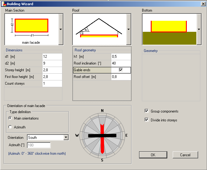
Again we assume a simple case with one heated slab-on-ground zone and an inclined unheated attic. Just enter the same inputs as in Figure 5 for you building in the Building Wizard.
Using vertices
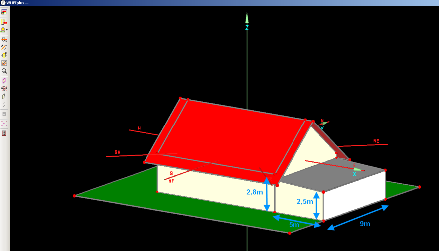
The simple building created with the [[Plus 2.X:Building#Building Wizard|Building Wizard] shall be expanded. The building extension will serve as fitness studio. The readily expanded building should look like the one shown in Figure 6.
Creating it you need to work with vertices. For more information on this topic, click here.
By copying and moving preexisting vertices and components and by creating new vertices and components, any desired building geometry can be generated. Of course there are several possible procedures to create the desired building extension.
One way to proceed is shown in the first movie.
Te other movie gives an overview on working using the 3D Edit.
STEP four: Windows
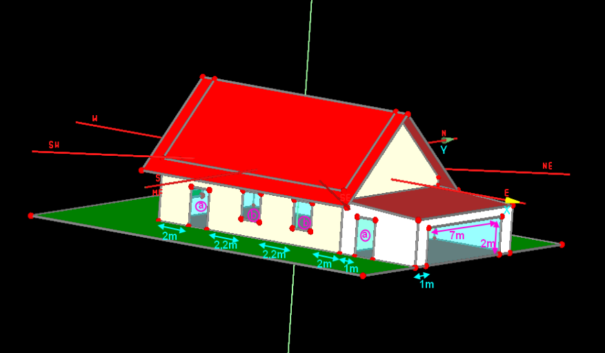
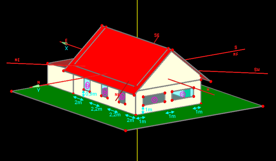
The building must be staked out with windows as well. The following pictures show you how windows should be placed along the walls. Measurements are
| WINDOW | length [m] | height[m] |
| a | 1,2 | 2,1 |
| b | 1,2 | 1,5 |
| c | 3 | 1 |
Try to get the windows right yourself. If you need help doing it, consult the chapter on windows. The following film shows you how to place the windows in the right way.
STEP five: Creation and assigning of the zones
The geometry of the building is complete. The next necessary (and highly important) step is to generate appropriate zones for the building and to assign them to the respective components. This is important for our building as there are two different way of utilization in our building; one part of it as living space, the other as fitness studio. Therefore the upcoming loads and requirements concerning heating, cooling, ventilation and humidification etc. vary greatly. This makes it necessary to distinguish between the two different sections in order to get reasonable calculation results. This is done by creating two different heated zones. The task of assigning the right zones to components is quite complex as a lot of tools and functions of WUFI can (or must) be used to succeed.
The following movie shows step by step how the assigning of the appropriate zones to the components is carried out. It also gives a good overview on all the tools and functions that help you do this.
Steps:
- generate zones
- check orientation of components (using the normal vector)
- assign zones (or climates) to the right side of the components
- allocate different colors to different zones for better understanding
- assigning (best in the tree)
- ungrouping (middle wall)
- show the whole building/ only one zone
- conditional not visible/pickable
- colors (default, own)


