Plus 2.X:Visualized Components
Visualized components
All components of the building requiring a definition of structure, material or environment are listed under "Visualized Components" and need to be edited here. Clicking on the respective component in the entry window table or the in the navigation tree opens the component to define. In the input window the component’s properties are defined. There are three possible types:
- Opaque components (walls)
- Transparent components (windows)
- Openings (not relevant)
There are various tabs to input all necessary data:
Opaque components
General
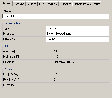
In the tab "General" the component it is named and assigned to a component type. There are three possible types:
- Opaque components (walls)
- Transparent components (windows)
- Openings (not relevant)
The type can either be changed this way or in the Properties of the component. For instance a french door could be converted into a opaque door this way.
Information needs to be made about inner and outer side of the component (read more:Properties). "Data" and "Parameters” inform about component data that can be adjusted in the other tabs.
Assembly
In the next tab the "assembly" of the construction is set.
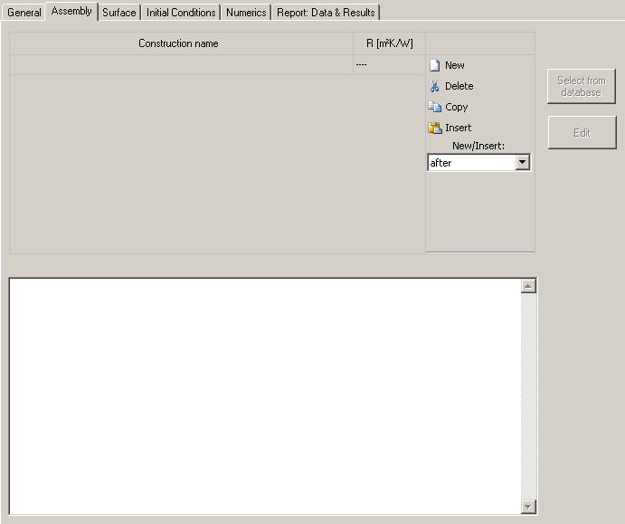
The project construction list is found under assembly. It contains all constructions (=assemblies) used in the project. The highlighted one is applied to the respective component. With "New" a new construction is created and appears in the list.
Assembly from Database
The appropriate assembly of the component can be loaded from the database. By "Select from database" you get to the Database Assemblies, where you can choose an assembly and either double click on it or on "Apply" to assign it. This assembly can of course be alterd using the "Edit" button (see next chapter)
Creating a new assembly with "Edit"
In case the desired assembly does not exist in the database a new one can be defined by clicking on the "Edit" button. The "Edit Assembly" window opens.
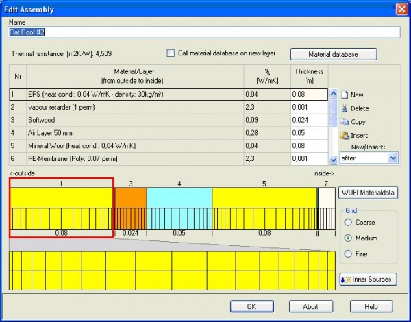
The new assembly needs to be named. Again with "New" a layer of material can be added and chosen from the
"material database". A thickness must be assigned to each layer.
Setting of the size of the numerical grid (coarse, medium, and fine) is also possible adjusted.
Heat, moisture and air change occuring inside a component can be included in the calculation as an internal source. The sort of the source can be selected in the drop-down menu in the dialog "Inner Source". Heat and moisture sources can be attached to one or more elements in one layer or to the entire layer under "Spread Area". If it is attached to one layer, the depth in layer of the element must be entered, for more elements the start end depth in layer must be inputted. Else "whole layer" can be chosen as well.
The source type must be defined, too:
- For moisture you can either choose "Fraction of Driving Rain", for which a fraction factor must be entered (intensity is defined as the percentage of incident rain)or "Transient Moisture Source from File", where you can use data from predefined files by entering the right file and column as well as a conversion factor.
- for heat you can either identify the source as "Fraction from Incident Solar Radiation" and enter a factor for it (intensity is defined as the percentage of solar radiation) or a inner heat source can be chosen from Files/Measured Data by check-marking "Transient Heat Source from File". Again, the right file and column and a conversion factor must be inputted.
- for air exchange either a constant value can be entered or to use external data "Transient Air Change from File" can be checked. For this enter right file, column and a conversion factor.
If "Group Components" was check marked in the Building Wizard components of the same type are automatically assigned to the same assembly. If this is not requested the components need to be ungrouped
Annotation: If there is no fitting assembly and it is necessary to define a new one it may be more reasonable not to use the "Edit" Button but to save the user-defined assembly right into the database, as it can be reused arbitrarily.
Surface
Thermal
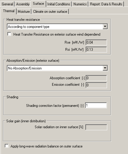
The hygrothermal transfer resistance can either be entered user-defined or be generated according to the component type.
Other important information are absorption and emission of the outer surface. These factors are used to calculate the radiation. If there are no user defined values available you can select predefined values from a list with typical exterior surfaces.
The shading factor is a reduction of solar radiation on the component, for example, by planting or other buildings. The factor is set to 1 (no shading) by default but can be altered
Solar Gain of the inner surface can only be entered user defined if you select "user defined" for the distribution of solar gains in Other Parameters.
Also long wave-radiation balance can be applied to the outer surface. However, make sure to have appropriate values for atmospheric counter radiation in the climate file you use before enabling the explicit radiation balance. Otherwise unrealistic temperatures may result at the exterior surface.
Moisture
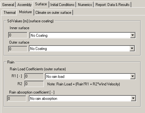
In the tab "Moisture" hygric properties of the component surfaces are defined. A Sd-value can be specified for the interior and exterior surfaces of the component when the coating is not already included in the assembly. Again there is a list of predefined coatings to choose from and else a user defined value can be entered.
If the rain load is taken into account it is calculated from normal rain, wind and the driving rain coefficients. The rain absorption is generated dependent to the component orientation.
Climate on outer Surface
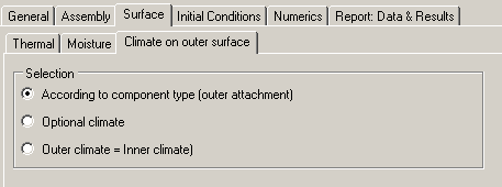
Each component has a inner and a outer side per definition. For more information about this see the chapter about zones. Information about the outer side needs to be made. There are three possibilities to choose from:
- According to component type (outer attachment): Information about the inner and outer side of a component were already made in the Tab "General". Choosing this option, WUFI calculates according to this information.
- Optional climate: An optional climate, created by the user, can be assigned to the outer side of the component as well. (This is for example necessary for a base plate of a building, it could have "ground" as information about its outer side and then needs an optional soil climate attached to it.)
- Outer climate = Inner climate: Choosing this option causes WUFI to assume that the climate on the outer surface is the same as that on the inner.
Initial conditions
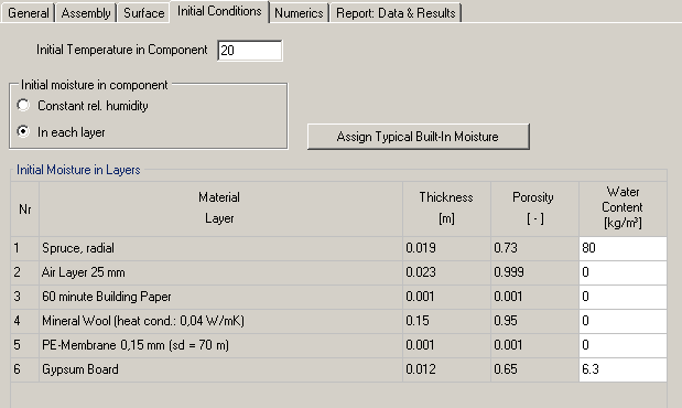
The "Initial Conditions" are important to start the calculation. Initial temperature and moisture in the building must be set. The humidity can be assumed constant over the component or the conditions in the material database are included.
Numerics
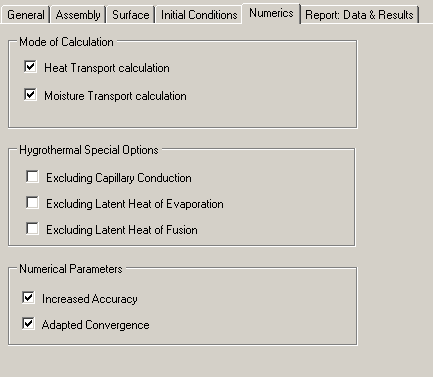
Under "Numerics" it can be selected whether the heat transport and /or moisture transport are to be calculated. Special hygrothermal options such as capillary or latent heat by evaporation or melting can be turned on and off. The incidence of convergence errors may require an adjustment of numerical parameters. By choosing increased accuracy and adapted convergence this can be avoided. However, before the adjustment of the numerical grid should be checked.
Report
In tab "Report: Data & Results" all settings are shown and after the calculation results for the respective component can be found here. If "Retain calculation results" is check marked, films (the ones you can see during a calculation) and graphs are retained and excel export is possible as well. Note that this takes a lot of memory and slows the calculation up. For more information check the resultschapter.
Transparent components
The procedure is very similar to that of opaque components yet there are differences.
General
This Tab is very much like the Tab "General" of the opaque components, the only difference is, of course, that the Type is "transparent".
Window Parameters
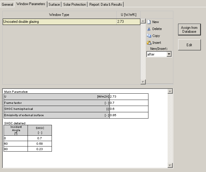
All the window types used in the project are shown in this list. The highlighted one is applied to the respective transparent component. A window type needs to be assigned to the transparent component. It can be chosen form the database or edited user defined. Also a window type can be chosen from the the database and modified individually.
To use a predefined window type click on "Assign from database" and pick the requested one from the windows database
However, if there is no suiting window in the database parameters defining a suitable window type can be entered in the "Edit window parameters" window which pops up after clicking "Edit".
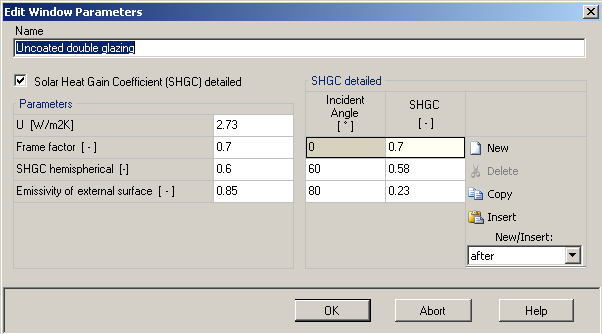
The SHGC can either be entered detailed, which enables the user to enter SHGC coeffients according to incident angle of solar radiation. For explanations on modifiying a profile, click here.
Besides U-Value, a frame factor (a factor for the proportion of glass of the whole window) , SHGC average (only if "enter SHGC in detail" is not check marked, a SHGC hemispherical value, and a value for Emissivity of outer surface can be inputted.
Surface
Thermal
Datei:P2-win-surface-thermal.png
The heat transfer resistance can either be entered user-defined or be generated according to the component type.
The shading factor is a reduction of solar radiation on the component, for example, by planting or other buildings. The factor is set to 1 (no shading) by default but can be altered
Solar Gain of the inner surface can only be entered user defined if you select "user defined" for the distribution of solar gains in Other Parameters.
Also long wave-radiation balance can be applied to the outer surface. However, make sure to have appropriate values for atmospheric counter radiation in the climate file you use before enabling the explicit radiation balance. Otherwise unrealistic temperatures may result at the exterior surface.
Climate on outer Surface
See the "Surface" chapter of opaque components
Solar Protection
Solar Protection
Window overhang
Report
In tab "Report: Data & Results" all settings are shown and after the calculation results for the respective component can be found here. If "Retain calculation results" is check marked, films (the ones you can see during a calculation) and graphs are retained and excel export is possible as well. Note that this takes a lot of memory and slows the calculation up. For more information check the results chapter.
