2D:Dialog Geometry
Dialog: Geometry
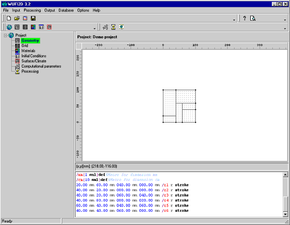
This dialog serves to define the two-dimensional geometrical arrangement of the individual elements which make up the construction and which are filled with the appropriate materials in a later step.
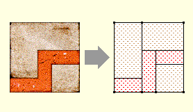
The construction has to be built up from rectangular elements. More complicated shapes must be broken down into rectangles:
The construction is most easily defined by drawing the constituent rectangles in the graphics area of the present dialog. Fine-tuning can later be done by editing the graphics script that is automatically generated by WUFI in the lower part of the dialog as you draw the construction.
Add a new element: the first rectangular element can be drawn at any
location of the graphics area. Any subsequent elements must have at least one
corner point in common with an existing rectangle: point the cursor at
an existing corner, marked with a dot, and drag the rectangular outline to the
intended shape. Refer to the rulers along the borders for proper dimensioning.
The dots are 'magnetic' to help you in precisely positioning the cursor.
You may delete a rectangle by removing its description from the graphics script
below.
The construction as a whole need not be rectangular.
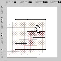
Scroll: Press the CTRL key and the left mouse button, and drag the graph of the construction into a convenient position.
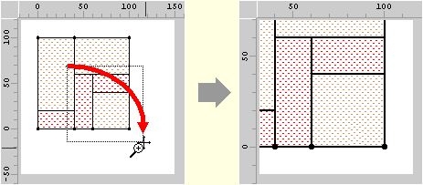
Zoom in: Press the SHIFT key and the left mouse button, and drag a zoom frame over the part of the construction to be zoomed, moving from top left to bottom right.
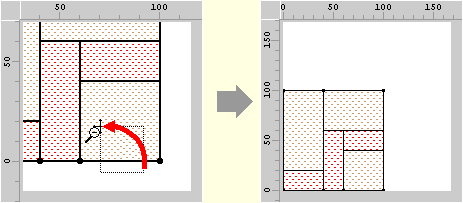
Zoom out: Press the SHIFT key and the left mouse button, and drag open a zoom frame of arbitrary size at an arbitrary location, moving from bottom right to top left. This will reset the magnification to default and undo any scrolling.
Tips:
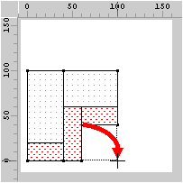
It will be useful to put the lower left corner of the assembly at the
coordinate origin (0, 0); this makes it easier to match the desired dimensions
of the assembly and its elements to the coordinates displayed on the rulers and
used by
the graphics script.
If you shift the home position of the coordinate
origin a small distance away from the coordinate origin (say by (100, 100)), then
after zooming out the construction will stay clear of the edges of the graphics
area and allow easier access for editing.
This graphical interface provides an easy way for defining and positioning the elements of the construction. If you need finer control you may edit the graphics script that is automatically generated by WUFI in the script window in the lower part of the dialog as you draw the construction.
